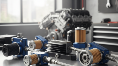
Industrial oil rarely fails without warning. Darkening, rising heat, noisy bearings, or clogged valves can point to contamination. Yet appearance alone can mislead. Fine particles and dissolved water may remain unseen. Oil filtration systems help control wear and support equipment reliability when selected and maintained correctly. They are not a cure-all.
This guide reviews seven options for industrial use, from portable kidney-loop units to fixed, high-flow filtration skids. Each design serves a different duty. A compact cart may suit a hydraulic reservoir during scheduled cleanup. A high-capacity system may better serve circulating oil on a production line. The right choice depends on oil viscosity, required flow rate, particle targets, water exposure, operating temperature, and filter media compatibility. Compare these factors with equipment guidance and the actual contamination load, not just a brochure’s headline rating. Ratings need context.
We also consider service access, replacement-element cost, pressure drop, monitoring, and how easily operators can verify performance. A filter that looks impressive but is rarely maintained can disappoint. That detail is easy to underestimate. No system removes every contaminant in every condition, and filtration cannot repair worn seals or correct poor storage. Use these comparisons as a practical starting point, then confirm requirements with a qualified maintenance or lubrication specialist. There is room for judgment here. The best fit depends on the plant, the oil, and the way equipment is actually used.
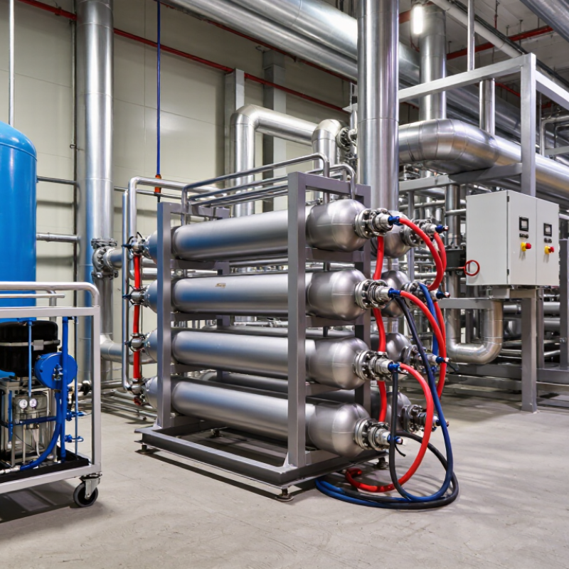
7 Best Oil Filtration Systems for Industrial Use
Industrial Oil Filtration: Purpose and Operating Principles
Industrial oil filtration protects pumps, bearings, and valves by reducing particles that accelerate wear. Dust, metal fragments, and oxidation residue can enter oil during operation. Even small contaminants may scratch close-fitting surfaces or restrict narrow passages. Clean oil helps equipment run reliably and can extend service intervals, though filtration cannot reverse chemical breakdown or remove every dissolved contaminant.
Most systems move oil through a filter element, where particles are captured as fluid passes through porous media. The element’s rating indicates the particle size it can retain under specified test conditions; it does not guarantee removal of every particle that size. Some setups also use water-removal stages or magnetic collectors. Flow rate, oil viscosity, operating temperature, and pressure drop all affect performance. A rising pressure difference across the filter may signal loading, but readings need context. A replacement schedule can look tidy on paper; actual duty cycles vary.
Tips: Check pressure gauges and inspect filter elements during planned maintenance. Sample oil periodically for particle count and water content. Match the system to the oil and equipment, and do not treat a cleaner-looking sample as proof that the oil is healthy.
Industrial oil filtration removes contaminants to help maintain fluid cleanliness and protect equipment. ISO 4406 codes classify cumulative particle counts per millilitre; lower codes indicate cleaner oil. The chart shows the upper particle-count limit for each code band.
Particle counts are cumulative at sizes greater than 4, 6, and 14 μm(c). Values are particles per millilitre and represent the upper boundary of each ISO code band. Required cleanliness depends on the equipment and operating conditions.
Industrial oil filtration uses several technologies because contaminants behave differently. Particle counters and oil samples help identify whether the main problem is dust, wear metal, or water. Surface filters catch particles near the media face, while depth filters trap them through a thicker, porous structure. The right choice depends on particle size, oil viscosity, flow rate, and the cleanliness target. Small details matter. A filter that works well with warm, thin oil may restrict cold, heavy oil.
Water calls for different treatment. Coalescing elements gather small water droplets into larger ones that can separate from the oil. Vacuum dehydration removes water and some dissolved gases under reduced pressure. Centrifugal separators use rotation to divide oil, water, and heavier solids by density. Magnetic traps can capture ferrous wear particles, but they will not remove sand or nonmagnetic debris. No method is universal. In practice, combining technologies may be useful, though added equipment brings maintenance and operating costs. Check pressure drop, element condition, and oil samples over time; a clean-looking sight glass alone cannot confirm that the oil meets a machine’s needs.
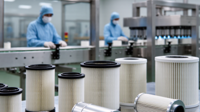
Industrial oil filtration is not one machine doing seven jobs. Pressure filters capture particles as oil passes through replaceable media, while depth filters trap debris throughout thicker filter layers. They suit different contamination loads and flow rates. Check the media rating against the equipment maker’s requirements.
Vacuum dehydration systems remove water and dissolved gases under reduced pressure. Centrifugal separators use spinning force to separate water and heavier particles. Coalescing systems gather small water droplets into larger ones for removal. Magnetic filters catch ferrous wear particles, but they will not remove nonmagnetic dirt. Kidney-loop systems continuously circulate oil through a separate filtration unit. Useful, but they still need routine checks.
Look at the oil, not just the equipment label. A cloudy sample from a hydraulic reservoir may call for water removal, while metallic debris near a gearbox may justify magnetic separation alongside particle filtration. Monitor pressure drop, flow, temperature, and oil condition; a clogged element can restrict flow. Keep service records, too. Small details matter. One limitation is easy to overlook: no single system addresses every contaminant. Match filtration to the fluid, operating conditions, and maintenance schedule, then verify results with regular sampling.
| System Type | How It Works | Main Contaminants Addressed | Typical Performance or Configuration | Best-Suited Applications | Key Consideration |
|---|---|---|---|---|---|
| Pressure filter | Uses a pump to drive oil through a replaceable filter element. | Solid particles such as dirt, wear debris, and oxidation products. | Elements are available in a range of micron ratings; particle-removal efficiency depends on the element’s rating and beta ratio. | In-line protection for hydraulic, lubrication, and circulating-oil systems. | Choose an element compatible with the oil, flow rate, pressure, and required cleanliness level. Standard particulate elements do not remove dissolved water. |
| Duplex filter system | Uses two filter housings and a changeover valve so one side can operate while the other is serviced. | Solid particles, using the selected filter elements. | Provides continuous filtration during element changes; filtration capability is determined by the installed elements. | Processes that require uninterrupted oil circulation, such as critical machinery lubrication. | Requires correct valve operation and enough capacity in the active housing to handle the required flow. |
| Vacuum dehydration unit | Heats oil as needed and exposes it to a vacuum, encouraging water and dissolved gases to separate from the oil. | Free, emulsified, and dissolved water; dissolved and entrained gases. Many units also include a particulate filter. | Water removal depends on oil temperature, vacuum level, flow rate, and the starting condition of the oil. | Oil reservoirs affected by moisture or gas contamination, including turbine and hydraulic systems. | Check oil temperature limits and material compatibility. Fine-particle removal depends on the unit’s separate filter stage. |
| Centrifugal separator | Spins oil at high speed so denser contaminants separate from the lighter oil under centrifugal force. | Free water and relatively dense solid particles. | Separation depends on the density and size of contaminants, oil viscosity, and operating conditions. | Applications with recurring free-water or heavy-solid contamination and suitable oil-flow conditions. | Generally less effective for dissolved water and very fine particles than dedicated dehydration or fine-filtration methods. |
| Coalescing separator | Combines small water droplets into larger droplets that can settle or be separated from the oil. | Free and some emulsified water, depending on the oil and system design. | Water-separation performance varies with oil chemistry, temperature, flow, and emulsion stability. | Oil systems where water droplets can be separated after coalescing. | Not intended to remove dissolved water; some additives or stable emulsions can reduce separation performance. |
| Magnetic separator | Uses a magnetic field to capture ferrous wear particles from the flowing oil. | Magnetic iron and steel particles. | Works only on magnetically responsive particles; capture depends on particle size, field strength, and flow path. | As a supplementary measure for detecting or reducing ferrous wear debris in machinery oils. | Does not remove non-ferrous particles, water, or dissolved contaminants and is usually paired with other filtration. |
| Depth-media filtration system | Passes oil through a thick, porous media bed that captures contaminants within the media structure. | Fine suspended particles; selected media can also absorb water or other specific contaminants. | Available in different media grades and designs; capacity and removal efficiency depend on the media and contaminant load. | Offline oil conditioning, polishing, and targeted removal of fine contamination. | Confirm that the media is suitable for the oil and contaminant. Water-absorbing media has a finite capacity and needs monitoring. |
Selection note: These are established industrial filtration and separation approaches, not a universal performance ranking. Actual results depend on oil type, viscosity, temperature, contamination, flow rate, filter rating, and system design. Confirm operating limits and required cleanliness targets with the equipment documentation.
Comparing industrial oil filtration systems starts with the fluid and the machine, not the smallest advertised micron rating. Check whether the rating is nominal or absolute, and ask how it was measured. Then compare capture efficiency at the particle sizes that matter to your equipment. A filter that performs well in a laboratory may behave differently with cold, viscous oil or changing flow rates. Look at dirt-holding capacity and pressure drop, too. A rising differential pressure can signal a loaded element, but it may also reflect a cold start. Details matter.
Operating cost includes more than replacement elements. Track energy use, labor, oil sampling, disposal, and any production time lost during service. A finer filter may protect sensitive components, yet require more frequent changes if contamination loads are high. Compare total cost per operating hour across similar duty cycles, rather than comparing purchase prices alone. Numbers can mislead. Record pressure and particle counts before and after installation, then review them over several service intervals. That takes patience. It can also expose a weak assumption in the original estimate. One practical limit: results from one machine may not transfer neatly to another, even when both use the same oil.
Choosing an industrial oil filtration system starts with the oil, not the catalog. Record the lubricant’s viscosity, operating temperature, flow rate, and contamination sources. Then set a cleanliness target using ISO 4406 particle codes. A fixed hydraulic unit may suit an in-line filter, while a large reservoir can often use an offline loop without stopping production. Check the filter’s beta ratio and pressure rating; a micron number alone does not show real capture performance. Small details matter. Water needs separate attention, since particle filters may not remove dissolved moisture.
Maintenance should follow measured conditions, not a calendar alone. Take oil samples from the same warm, circulating point, and trend particle counts, water, and filter differential pressure. Replace elements when pressure limits or condition data call for it, rather than waiting for visible dirt. DOE’s Operations & Maintenance Best Practices guide reports broad predictive-maintenance benchmarks: 25–30% lower maintenance costs, 70–75% fewer breakdowns, and 35–45% less downtime. These are not filtration-specific guarantees. One practical flaw is easy to miss: poor sampling can make a healthy system look dirty—or hide a developing problem. Keep records, inspect seals, and verify that bypass indicators work. A clean-looking oil sample is not proof.